|
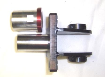
BELT TENSION BRACKET IMPROVEMENTS
 1.
We replace all 16 of the original tension brackets with
newly designed brackets. 1.
We replace all 16 of the original tension brackets with
newly designed brackets.
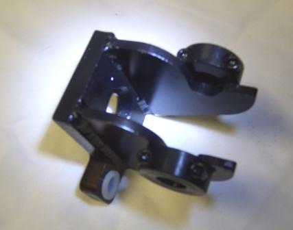
2. The new
brackets are laser cut and then heliarc welded in a
fixture to insure the layout of all the holes are the
same.
3. They
utilize split collars to clamp the idler wheel axles in
place to eliminate any looseness that would affect
feeder belt tracking or the axle spinning that would
cause damage to the bracket itself.
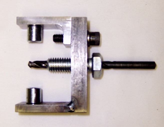
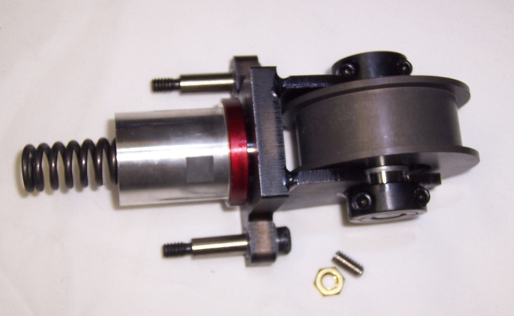
4. The
bracket has replaceable bushings which slide on the
original shoulder bolts. If the threaded holes for the
shoulder bolts are worn or damaged in your machine, we
supply a repair kit with a drill and tap fixture for
inserting threaded inserts.
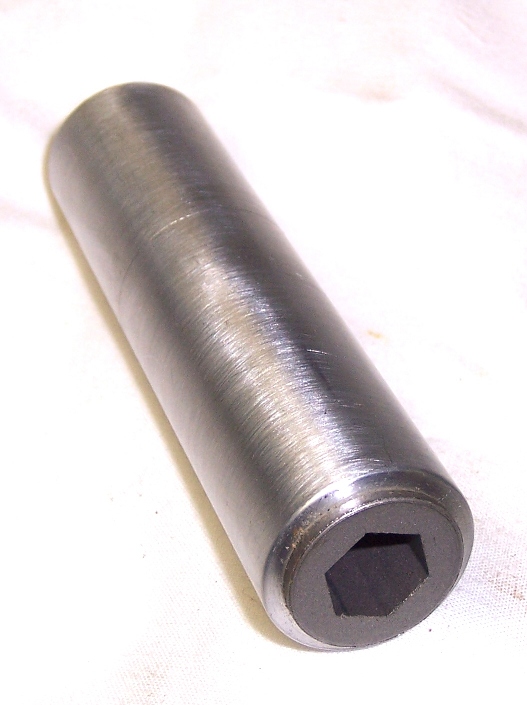
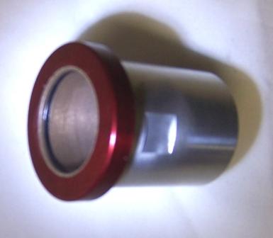
 5.
The new brackets also utilize a specially machined
Linear bearing with O-rings and linear bearing shafting
to hold 5.
The new brackets also utilize a specially machined
Linear bearing with O-rings and linear bearing shafting
to hold
 the
Idler tension pulley in line. the
Idler tension pulley in line.
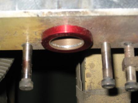
6. These
brackets do not require any modification to your
machine. Simply remove the original tensioning spring
and use the supplied flex-hone to deburr the bore. Then
slip this new bearing in and lock in place with a set screw in one of the tapped holes formerly
used for the jib plate.
with a set screw in one of the tapped holes formerly
used for the jib plate.
7. We supply
new tensioning springs which are inserted inside the
linear shafting and with an O-Ring in the Linear bushing
the system is sealed and can be permanently lubricated
at installation.
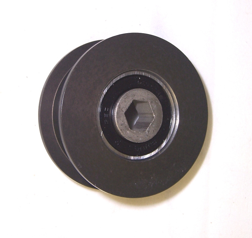
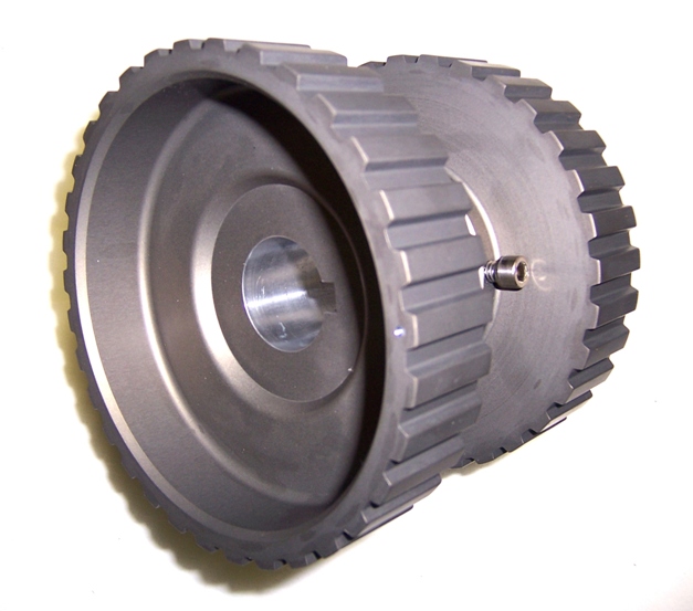
8. Tensioning
idler wheels are precision CNC machined from 6061
aluminum, Hard
Coated and Teflon Coated.
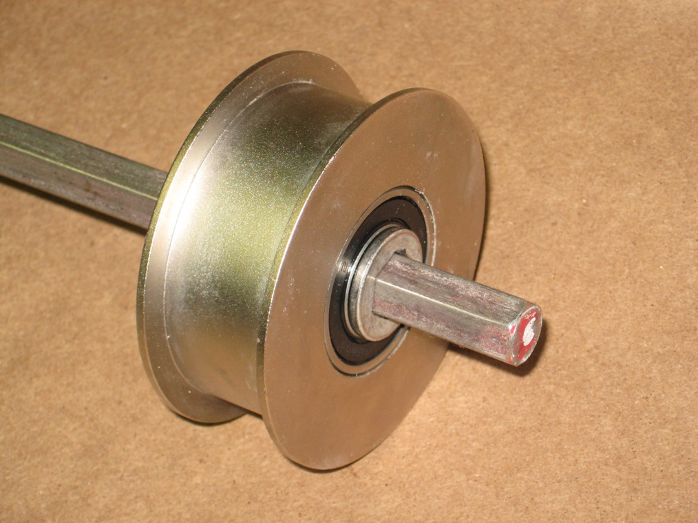
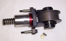 9. They have
two each 6202 ball bearings installed in them instead of
bushings. This adds longer life keeps wheels aligned. 9. They have
two each 6202 ball bearings installed in them instead of
bushings. This adds longer life keeps wheels aligned.
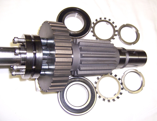
10.
They also come assembled with a ground and hardened
axle. |